Lire en Français !
Files:

Home
Planes and Vortex
Aircraft Drag
Induced Drag
Vortex in Action
Wake Turbulence
Wingtip Devices
Patent Abstract
French & WIPO Patent
Results
Minix WAKENET2 France/Europe
Minix WAKENET2 USA
Test Images
Test Videos
Minix Applications
Minix and Wind Turbines - Results
Shows
News
Henry FORD Prize
Roland PAYEN Prize
Commercial Aviation
Jumbo-Jets
Business jets and light aircrafts
Homebuilt aircrafts
Future of Aviation
Seen on the web
Wind Turbine's Noise
The differents drags of an airplane

The table below lists all the items that you find in this document. Click to go there directly.

1 - The drag 8 - The drag friction
2 - The drag coefficient 9 - The profile drag
3 - The curve of drag 10 - The wave drag
4 - The aileron drag 11 - Induced drag
5 - The shock drag 12 - The minimal drag
6 - The boundary layer drag 13 - The parasite drag
7 - The drag of shape et coefficient  

1 - The drag:
This is the component parallel to the direction of flow.
The drag has always posed problems to fly, all engineers focus their work to reduce this resistance on all parts of an airplane.
A plane without any drag is a pure uthopie.
To do fly a plane, it's simple, just adapt a propulsive force equal to its total drag, ie the addition of the drag of wing at the parasite drag.
When talking about drag this includes the total drag that is the sum of drags of the wing (Cxi) induced drag , fuselage (CxF), the stab (CxS) and a drag known of interaction between the wing and the fuselage and the stabilizer (Cxl)
 
2 - Calculation of the drag:
Cx being the drag coefficient
? being the density of air (kg per cubic meter)
V being the velocity in meters per second
S being the area in plane of the wing
The formula of the drag is summed up by Cx 1/2 r Vē.S

Calculation of the total drag:
Total Cx = Cxi + CxF + CxS + Cxl

In First calculate the Cxi from a Cz 0.3 (lift coefficient any):
Cxi = Cz² / 7.7 (aspect ratio of the aircraft) = 0.09 / 7.7 = 0.0116

Now the CxF:
CxF = 0.006/racine square of wing surface (18.7 m²)
CxF = 0.006/4.32 = 0.0013

and also the CxS:
CxS = Cz² s / aspect ratio , ie:
Cxz = 0.09x18.7 / 7.7 = 0.0116

and finally the Cxl:
Cxl = 0.1 of Cx total (0.2314 x0, 1) = 0.0231.

Total Cx = 0.0116 + 0.0013 + 0.0116 = (0.0245 + 0.0024)) = 0.0269

The Cz being 0.3 and the total Cx of 0.0269. It Fineness (Cz / Cx) at 200 km / h will be of 11.15.

The total Cx of this aircraft that is 0.0269 and at a speed of 200 km / h (55.55 m / s) following the formula above:
0.0269 x 0.5 x 1.225 x 3086 x 18.7 = 950 N
Computing power required: 950 x Vm / s55.55 = 52,772 Watts
Computing power horse 52772/736 = 71.70 horses.

3 - The curve of drag :
at 0 ° the drag is minimal and even slightly negative and increases in both directions from this angle and until around 6 ° the increase of this drag is not very fast, then it becomes more and more pronounced especially after the stall angle, when the flow becomes turbulent.

4 - The aileron drag :
Suppose the plane is close to the stall angle, and the pilot decided to turn left: it moves the handle to the left (which lowers the right aileron and lifts the left) and at the same time it puts foot at left . The rudder will make an effort without much conviction to turn the aircraft to the left, but what will be the effect the moving of ailerons?
By lowering the right aileron should increase the lift on the right wing, but in practice, it may reduce it by increasing the angle of attack beyond the angle of maximum lift . But what is absolutely certain is that the drag of the right wing increases dramatically and tends to hold the wing to rotate the aircraft to the right. This effect yaw due to aileron drag, exists at all angles of attack, but it is particularly marked when the aircraft is close to stalling. It's called inverse yaw

5 - The shock drag :
The additional drag that characterizes the stalling by shock wave is of the same nature as form drag and the drag friction ie it opposes the movement of the body in the air by applying forces or perpendicular or tangential to the surfaces. However, although the end result is the same, the shock wave and the drag resulting are phenomena are directly related to the approach the speed of sound. This additional drag is so great that refers to a particular term : the shock drag

6 - the boundary layer drag :
We consider that the shock drag consists of two parts: the wave drag, which is the drag generated by the production of a wave, and what could be called the boundary layer drag, which is the friction drag produced by the thickening of the boundary layer. These drags correspond to those shape and friction, than, of course, are still present beyond the stall by shock wave, although their amplitude is relatively small compared to the shock drag .

7. The drag of shape
It is this part of the resistance that is due to the fact that when a viscous fluid flows around a solid object, vortices are formed and the threads of the flow are no longer smooth. It is essential that the form drag is minimized over all parts of the aircraft that are exposed to air. For example a plate perpendicular exposed to the relative wind, has a resistance of 100%, a cylinder at 50% , a tapering shape at 15%, a profile.at 5%

7bis - Theoretical value of K:
This formula expresses the fundamental relationship between the air flow around a body and the forces applied to the body. It is a perfect illustration of the relationship that we can be a new found between theory and experiment. In studying the mechanics, the reader has probably had to solve problems where we had to find the pressure exerted by a jet of water on a wall perpendicular to the jet. According to Newton's second law, the force applied to the wall is given by the rythme of change of momentum of the jet. Now suppose we do the same thing with air. Let V (m / s) the speed of the air flow and S (m²) the area of the plate (Fig. 2.18). Assuming that all of the air that moves to

Fig. 2.18 Anémomètre rustique
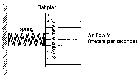
Fig. 2.18 Anemometer rustic

the plate meeting it actually, assuming that the air particles are not at all elastic that is, that they don't rebound and that they leave the plate, that is to say, they do not bounce and it leaves the plate by sliding parallel to its surface, and assuming also that nothing else happens behind the plate, we can say that the volume of air which meets the plate in a second, is of VS cubic meters, if r is the density, that is, means the weight of a cubic meter, the air mass which meets the plate in a second is of r VS kg.


The movement quantity of this air mass is r = VSxV = rSV².

Therefore, the movement quantity lost by the air in one second is equal to r SV² and, according to Newton's second law, the force on the plate is equal to r SV² newtons.

So, with all these assumptions, the value of K would l. But if we assumed that the air was perfectly elastic and that it bounced at the same speed after meeting the plate, the change of movement quantity of the air would have been double. the force on the plate r SV² and K = 2. In both cases, the error is significant when we know that the value of K for a flat plate, as determined by laboratory tests, is approximately 0.6. The error does not come from theoretical principles involved but our assumptions about what is happening, because they are all false! It is remarkable that the theoretical value of K is greater than that found experimentally. this proves that the greatest error occurs because it is assumed that all the air that approaches of the plate, indeed to meet it and stop it. The experiments show that most of the air escapes through the edges of the plate, and the flow then becomes turbulent.

The reader surely wonders why we do not just experimental facts when theory gives so much erroneous results . The truth is that we relies almost entirely on the results of the experiment when we studying the aerodynamics phenomena, but the theory, as in this case, gives the nature of the law and the experiences give the constants or the coefficients . Here, the theory states that the force on the plate is proportional to r SV² and the experience gives the important coefficient proportionality factor K.

7 ter- Bernoulli's Theorem
The Bernoulli's theorem offers us another interesting approach to this problem. He tells us that in the flow of an ideal fluid, that is to say, not viscous, the sum of the energy of position (or potential energy), of energy of motion (or kinetic energy) and of the energie of pressure remains constant. In cases that concern us, the changes of height of the fluid are not sufficient to produce a significant effect on the first term of this sum is to say the potential energy. Therefore, the sum of the first two terms should remain constant, which means that if all the kinetic energy is lost when the air meets the plate, it must be converted immediately into pressure energy

The kinetic energy of a mass of m kg moving at V meters per second is of ½ mV ² joules; kinetic energy of 1 m³ of air is ½ r V² Joules. If all this energy is converted into pressure energy, the pressure is of ½ r V² pascals, and if the surface of the plate is of S square meters, the total force applied on the plate will be of ½ r SV² newtons.

Again, we note that the theory indicates the nature of the law, but gives us the wrong coefficient. In this case, the main error is that we suppose the non viscid fluid, the theory does not take into account vortices formed at the back of the plate and that may well be responsible for the increase of K of ½ (its theoretical value) at about 0.6 (its experimental value). This is confirmed by the fact that in a Pitot tube - we will study it in the next sections - one obtains in practice the value of K = ½ with an extraordinary degree of precision.

8 - the drag friction
This is the flow resistance that present a thin and flat plate, parallel to relative wind.

9 - the profile drag
The form drag and the friction drag is a large part of the total drag of an aircraft and the major part in the field of high subsonic speeds. Sometimes, we give at the sum of these two drags the name of
profile drag, but we will avoid this term because it tends to give the impression that this is another name for the form drag as it also includes the friction drag.

10 - the wave drag
The wave drag and the boundary layer drag are part of the shock drag. This drag is generated by the production of a wave.

11 - induced drag and its calculation:
Always directed parallel to the relative wind. This is the main cause of trailing edge vortices : the air that passes on upper surface of a wing tends to flow inward. this is lt because the pressure on the upper surface is lower than the pressure outside of the wing tips. On the other hand, the air below the wing flows outwardly because the pressure on the lower surface is greater than that which prevails outside wingtips. The air continually seeks to circumvent the wingtips, of the intrados to the extrados. How we may explain why high elongation is better than low elongation would be say that more the elongation is tall the greater the amount of air that escapes through the wingtips is low. The air that bypasses the wingtips is no longer there to produce lift, this is sometimes called a "marginal loss".

As the two flows, these of the extrados and these of the intrados, meet them at the trailing edge at a certain angle, they forments vortices that rotate clockwise (viewed from the rear) behind the left wing and in the counterclockwise direction behind the right wing. All the vortices of the same side tend to join, to form a single large vortex which escapes from each wingtip. These two large eddies are called marginal vortices.

Most pilots saw these vortices, or more precisely, the central part of these, made visible by condensation. The humidity of the air condenses due to the pressure drop in the core of the vortex. It should not be confused those drags with the condensation produced by the gas ejected by engines at high altitude.

If we now consider the direction of rotation of these vortices, we see that there is a flow of air up, outside the wingspan and a current toward the down in the back of the trailing edge . Do not confuse this current toward the down with the deflection that occurs normally. In the latter case, the downwash is always accompanied by upward deflection in front of the wing so that the final direction of the flow is not changed. But in the case of the marginal vortices, the upward deflection occurs outside of the wing, and not in front of it, so that the flow leaving the wing is ultimately directed to the low. Therefore, the lift, which is perpendicular to the flow, is slightly inclined rearwardly and contributes to the drag. This part of the drag is called induced drag.

This induced drag is inversely proportional to the square of the speed, while the remainder of the drag is directly proportional to the square of the velocity.

How to calculate the coefficient of induced drag (Cxi)
First calculate the aspect ratio / Chord
Then calculate the coefficient of lift (Cz): Cz 1/2 r V².S
Then divide the coefficient of lift to the square by the aspect ratio.

How to calculate the resistance (Rx) in Newtons of the induced drag:
Multiply the induced drag coefficient by a 1/2, by the density of the air, by the speed in meters per second to the squared, and by the wing surface.
(Cz²/p A). 1/2 r V². S, the result is in Newtons
(N = equal to the force which a body having a weight of 1 kilogram an acceleration of 1 meter per second squared).

How to calculate the required power (in Watts) to oppose to this induced drag:
Multiply the resistance (in Newtons) by the speed (meters by seconds ) Rx.V.
It only remains to convert the Watts into horses.
horses (hp = 736 Watts or 75 kg per second).

12 - the minimal drag
One might think that to fly at the minimal drag it is just give at the aircraft the trim that allows it meet its the air in the best profile, in other words, the trim that produces the lowest drag . But if you think well about it, we quickly realize that this idea is wrong. This "trim that can present the best profile" involves a high speed, and we know that the effects of high speed, with respect to the drag, cancel the benefits that could be gained by presenting the aircraft to air in the good trim. We can say that it is this trim that achieves high speed and the high speed, however, is cause of the drag. It would be to do too much effort to try to go faster.

Moreover, it must not be imagined that produce the lowest drag flying at minimum speed in level flight. Indeed, the wing, at the minimum speed, at a high angle of attack, 15 ° or more, and the induced drag, to mention only one, is extremely high, then you must make a great effort too to keep the plane in the air.

There must to have therefore be a compromise between these two extremes: it would not be an aircraft if there was no way to compromise one way or another. It would not an aircraft if the solution was not obvious, provided that shows to us which way to look! Given that the lift must always be equal to the weight, that we assumed constant and equal to 50 KN, the drag is at minimum when the lift / drag , ie the fineness is at maximum. The fineness curve refers to wing profiles only. The fineness values will lower if we consider the aircraft as a whole, given that the lift will not be much greater than that of the wing alone, while the drag is considerably higher, perhaps double. In addition, variations in fineness depending on the angle of attack, that is, the shape of the curve will not be the same for the entire aircraft. Nevertheless, there is obtained a maximum value, say 12 to 1, for an angle of attack about the same as which given the best fineness of the wing alone (3° or 4°), and the curve redescents on each side of the maximum, so that the fineness is smaller, ie the greater drag, when flying at an attack angle smaller or larger than 4 °. In other words, the finesse decreases when flying at a speed greater or smaller than that corresponding to 4°, in the case of our aircraft, the table shows that this speed is 160 knots.

The angle of attack that gives the best glide remains the same regardless of altitude and weight and therefore the same range passable. It is simply to present the aircraft to the air at the best angle, and it has nothing to do with the density of the air, the load carried by the aircraft or even the method of propulsion.

Take an example: 7.600.000 J that we would want to obtain of a liter of fuel. The joule is the work done by a force of one Newton whose point of application moves one meter, we can calculate the distance traveled by aircraft with a liter of fuel by dividing our 7.6 million J by the total drag at varying speeds. At 100Kts 912 m , at 120Kts 1610 m, at 140Kts 1792 m, at 160Kts 1822 mn at 180Kts 1627 m, at 200Kts 1292 m, at 220Kts 1095 m, at 240Kts 912 m , 260Kts 790 m, at 280Kts 684 m ,at 300Kts 577m ,only. These figures are true regardless of the altitude. If the weight is 60 KN instead of 50 KN, each distance is divided by 60/50, that is to say 1.20. If the weight is less than 50kN, each distance will be proportionately greater

In summary, to obtain the maximum range, it must to fly at a determined angle of attack, ie at an indicated determined airspeed . It can fly at any altitude, but it must carry a minimum load, when it must to carry a greater load, it must increase airspeed.

13 - the parasite drag
Some divide of an other way the total drag of an aircraft. they do the distinguish between the drag of the wing, ie the drag created by the wings or other lift surfaces, and parasite drag that is the drag of parts that do not contribute to the lift. Older types of aircraft had a large portion of their total drag transformed into parasite drag


Last update : Agust 11th 2019
528535 Visits since its creation | 5 connected
Recommend this page | Print this page | Top of the page